Table of Contents
$\newcommand{orange}{\color{orange}}$
- Light is the smallest amount of energy that can be transported.
- It has wave-particle duality: it is both an electromagnetic wave and a particle, known as a photon.
- Visible light has a wavelength between 400-700nm.
- Light is created when an electron in its excited state drops back to a lower energy state and loses excess energy in the form of EM radiation.
- The moving charge of an electron creates an oscillating magnetic field perpendicular to an oscillating electric field.
Wave and Particle Models of Light
Newton’s Model of Light
Newton proposed that light was made up of tiny perfectly elastic particles, or “corpuscles”.
Newton concluded that travel in straight lines in all possible directions thus, they were particles not waves as waves propagate.
The rate at which they travel depend on the medium they are in.
Newton believed light must be a particle as it travelled in a vacuum and waves were believed to require a medium.
Reflection of light is just like the rebound of a perfectly elastic ball (explains equality of angle of incidence and angle of reflection).
Refraction was due to change in speed of particles caused by net attraction of particles to a medium with more matter however, he thought light travelled faster in denser mediums such as water.
When a ray is in a medium the ray moves in a straight line as Newton’s 1st Law states that the ray will not bend if no net external force (none since attracted equally on all sides).
Light splits due to the size of the particle (Theory of Fits), particles that fit between atoms of the medium would refract and light that could not would reflect.
He also said that different colours of light had different size particles thus, causing separation of white light to occur.
Light particles have an ambiguous, non-spherical shape which allows for polarisation.
The major issue of the Corpuscle theory was that Newton could not explain absorption.
Huygen’s Model of Light
- Huygen proposed that light was a wave that propagated perpendicular to its direction of travel and has a miniscule wavelength.
- Huygen knew that waves must have a propagating medium so Huygen called the medium for light the ’luminiferous aether’, which supposedly fills up all space thus, allowing light waves to travel.
We now know that this is incorrect, and that light does not need a medium to travel.
Huygen’s principle: Every point on a wavefront is a source for secondary semicircular ‘wavelets’ which spread out in the forward direction with the same speed as the wave. The new wavefront is the tangent to all the secondary waves. When part of the wavelets is blocked, the tangent is modified.
Reflection: When the wave meets the surface at an angle, new wavelets are created which form a new wavefront that propagates at an angle equal to the angle of incidence. Refraction: Wavelength increases as wave enters a denser medium. The new wavefront is shifted thus, light bends towards the normal (denser) or away from the normal (less dense). Predicted that light travelled slower in water than in air.
Diffraction: Waves are able to diffract, diffraction is due to wave interference. Little diffraction is due to small wavelengths and large slits which explains rectilinear propagation. A plane wave is an infinite superposition of spherical waves. Light diffracted when going around objects. If light was a wave, it would be able to diffract. The evidence for this was the blurred edges of a shadow which were not explained by Newton’s particle model but could be explained through wave interference in Huygen’s model.
Evidence: Poisson spot which is the brightest spot of a circular shadow located at the centre of the shadow when a point source of light is shone onto a ball or disc. This could be explained with waves as the waves diffract and then constructively interfere at the Poisson Spot leading to a bright spot where there isn’t any direct light source.
In 1850, Foucalt also showed that light slowed down when it entered water from air, as predicted by Huygen’s model. Young’s Double Slit Experiment: Evidence for the wave nature of light includes reflection, refraction, diffraction, interference and polarisation.
Diffraction
- Process by which a beam of light is spread out as a result of passing through a narrow aperture or across an edge.
- It is observed when waves spend around the barrier or through an aperture.
- The most pronounced diffraction occurs when the size of the aperture is close to the wavelength of the incident waves.
- Diffraction is a feature of all waves.
- Diffraction gratings have parallel slits (gaps) which light passes through.
- As light passes through the gap it bends at the edges leading to destructive or constructive interference.
Single Slit Diffraction
- When monochromatic light (light of a single wavelength/frequency) is passed through a narrow slit, Huygen’s wavelets allow the wave to interfere with others as well as turn corners thus, causing an interference pattern on the screen.
- If one wavefront passes through the left of the slit and another from the right, when they meet, they will have travelled slightly different distances.
- This difference is the path difference.
- If wavefronts are aligned when they meet, they will constructively interfere, if they are out of phase by 180° they will destructively interfere.
- This interference causes the interference pattern.
- Most light energy is concentrated on central maxima (wave travels equal distance from both sides of the slit).
- A diffraction grating is when light passes through a number of slits.
- They’re used when light of different wavelengths needs to be separated at a high resolution.
- Light waves emerging from the gaps will interfere with light waves from adjacent gaps to create an interference pattern.
- They are used in spectrographs.
Condition for destructive interference for single slit
$d\sin(θ)=m\lambda$ where d is slit width (m) for single slit diffraction, θ is angle of diffraction, m is order of interference, $\lambda$ is wavelength (m)
Single slit wavelength
$\lambda=\frac{\frac{1}{2}yd}{mL}$ where y is node to node (1/2y is central bright to midline of dark), d is slit width (m), m is order of interference, L is distance from slit to screen (m).
Young’s Double Slit Experiment
In 1801, Thomas Young designed his double slit experiment on the basis that:
If light was a wave then when two rays of light meet there must be interference
The interference would either be constructive or destructive
He understood beat frequencies produced from soundwave interference and he wanted to test whether light would exhibit similar behaviour
For interference to be detected, Young concluded that the two sources must:
- Be coherent (frequency and waveform are identical)
- Maintain constant phase relationship
- Have the same frequency waves
- Have approximately the same amplitude
Method
- Sunlight was first shone through a single slit with a red filter to create a coherent light source (monochromatic and coherent)
- The light was then projected onto a detection screen through two miniscule slits which produced an interference pattern of bright and dark fringes on the screen
- Slits of different sizes and distances apart were then tested
- Young was able to calculate the wavelength associated with light as well as provide convincing evidence for Huygen’s wave model using: $y=\frac{m\lambda L}{d}$
- For small angles $L\gt d$ where y is antinode separation on screen (middle of one bright spot to next bright spot), $\lambda$ is wavelength, L is distance from slit to screen, d is slit width, m is order of interference (central maxima is 1, one to the right is 2, left is -2…).
- Or using $y=\frac{(m+\frac{1}{2})\lambda d}{d}$ for small angles $L\gt d$ where y is node separation on screen (dark to dark), m is order of interference, $\lambda$ is wavelength (m), L is distance between screen and slit (m) and d is slit separation (m)
Findings
This resulted in the formation of an interference fringe consisting of clear light and dark sections on an observation screen. The only way this could happen was if light was a wave because otherwise adding more light particles to an area should not produce a section of no light. The negative and positive sections of the interference pattern were due to constructive (bright light, in phase) and destructive (no light, 180 degrees out of phase) interference occurring. He was able to calculate the wavelength of light by using distances between 2 areas of constructive interference and 2 areas of destructive interference as y.
Path Difference: Difference in distance travelled by two waves to a point on the screen. Constructive interference occurs when the path difference is 0 or a whole number of wavelengths.
$\orange{\text{Path Difference}=m\lambda}$
Conditions for Constructive Interference for Double Slit
dsinθ = mλ where d is slit separation (m) for double slit diffraction, θ is angle at which constructive interference occurs, m is order of interference, λ is wavelength (m)
dsinθ = (m+ 1/2)λ where d is slit separation (m) for double slit diffraction, θ is angle at which destructive interference occurs, m is order of interference, λ is wavelength (m)
θ is angles at which constructive/destructive interference occurs (depends what formula)
Double Slit Wavelength
$\lambda=\frac{yd}{mL}\newcommand{deg}{^{\circ}}$ where y is central maxima to nearest antinode, d is slit width (m), m is order of interference, L is distance from slit to screen (m)
Diffraction gratings contain a large number of parallel, closely spaced slits or grooves.
They produce interference maxima at angles θ given by dsinθ = mλ where distance between slits is d, angle to a bright fringe of a particular colour is θ, m is order of interference, λ is wavelength
Relationships
- The central intensity is proportional to the square of the number of sources. (direct square)
- The smaller the wavelength RELATIVE to the slit, the less diffraction (direct)
- The greater the wavelength RELATIVE to the slit, the greater the diffraction (direct)
- Fringe separation is DIRECTLY proportional to wavelength/frequency of radiation forming it (direct)
- Width of the diffraction pattern is INVERSELY proportional to slit width (inverse)
- With double slit interference we still have a diffraction envelope, inside that there are the interference fringes.
- Spreading out of the diffraction envelope is determined by width of the slit whereas fringe separation is determined by space between two slits.
- Decreasing slit separation increases fringe separation (inverse)
- Increasing width of the slit, central maximum narrows (inverse)
- Increasing L (distance from screen to slit), increases fringe separation (direct)
- Decreasing d, increases fringe separation (inverse)
Polarisation
Polarisation occurs when a transverse wave is allowed to move only in one direction.
Light produced by a light globe or the sun comes out as waves in all planes.
A light wave that is vibrating in more than one plane is referred to as unpolarised light.
Such light waves are created by electric charges that vibrate in a variety of directions, thus creating an electromagnetic wave that vibrates in a variety of directions.
Polarised light waves are light waves in which the vibrations occur in a single plane.
The process of transforming unpolarised light into polarised light is known as polarisation.

Polarisation Calculations - Malus’ Law
- To find the intensity change produced by a single polarising filter, simply halve the original intensity
- If the light has already passed through one polariser and you are asked to find the intensity after a second polariser, use Malus’ Law:
$$\orange{I_{2}=I_{0}\cdot\cos^{2}(\theta)}$$
- Where $I_2$ is the final intensity (Wm), $I_0$ is the intensity before the first filter (Wm), and θ is the angle between the polarisation axes (left is negative).
- The first polarizing filter is called the polarizer, the second polarizing filter is called the analyser.
Factors that influence intensity of transmitted wave (I):
- Analyser angle
- Sinusoidal relationship when intensity of I is plotted against (y axis) analyser angle relative to polariser angle (x axis)
- When analyser is at angle of $0\deg$ relative to the polariser’s polarising axis, intensity is at a MAXIMUM of $0.5I_0$
- Intensity approaches zero as angle increases (inverse)
- The same angle either positive or negative, have the same impact on intensity of transmitted wave $(I_0)$
- $\frac{I}{I_0}$ vs $\cos^2(θ)$ gives a positive linear graph.
Forms of Polarisation
Polarisation by Filter
- A polarising filter only transmits components of the wave in a particular direction and absorbs the rest.
- A practical application is polarising sunglasses, which absorb light in a particular plane, reducing glare.
- The chemical composition of the polaroid filter allows one plane of waves to pass through and the other plane of waves parallel to the molecular alignment of the filter to be absorbed by the filter.
- When unpolarised light is transmitted through a polaroid filter, it emerges with one-half the intensity and with vibrations in a single plane.
- The polarisation axis is perpendicular to molecule alignment and extends across the length of the filter.
- It only allows vibrations of the electromagnetic wave that are parallel to the axis to pass through.
- Any vibrations that are perpendicular to the polarisation axis are blocked by the filter.
- The filter does not distort the shape or dimensions of the object; it produces a dimmer image of the object since one-half of the light is blocked.
- The angle between the direction of polarisation and the axis of a filter is θ.
Polarisation by Reflection
- Unpolarised light can also undergo polarisation by reflection off of non-metallic surfaces.
- Extent of polarisation is dependent upon angle of light’s approach and material of surface.
- The reflected ray is fully polarised horizontally (vibrating in a plane that is parallel to the surface of the material) at Brewster’s angle (angle of which reflected light is fully polarised, refracted and reflected beam are perpendicular, unique to each medium) as when the incident light crosses the interface, the light is absorbed temporarily by atoms in the second medium.
Chemists may recognise this phenomena as what occurs in the Flame Test from Chemistry Module 1.
- Electrons in these atoms oscillate back and forth in the direction of the electric field vectors in the refracted ray, perpendicular to the direction the refracted light is traveling.
- The light is re-emitted by the atoms to form both the reflected and refracted rays.
- The electric field vectors in the light match the direction the electrons were oscillating, and they must be perpendicular to the direction of propagation of the wave.
- When light comes in at the Brewster angle the reflected wave has no electric field vectors parallel to the refracted ray, because the electrons do not oscillate along that direction.
- The reflected wave also has no electric field vectors parallel to the reflected ray, because that’s the direction of propagation of the wave.
- The only direction possible is perpendicular to the plane of the picture, so the reflected ray is linearly polarised.

Brewster’s Angle
$$\orange{n=\frac{\sin({θ_i})}{\sin(θ_r)}=\frac{\sin({θ_i})}{\sin({θ_{90\deg-i})}}=\tan(θ_i)\text{, where:}}$$
- $n$ is the refractive index of the material from which the light is being reflected
- $θ_i$ is the angle of incidence
- $θ_r$ is the angle of refraction
Polarisation by Refraction
- Polarisation can also occur by the refraction of light.
- Refraction occurs when a beam of light passes from one material into another material.
- At the surface of the two materials, the path of the beam changes its direction.
- The light transmitted into the medium is partially polarised as it has lost the reflected light that is polarised by the reflecting surface.
- If an object is viewed by looking through an Iceland Spar crystal, two images will be seen.
- The two images are the result of the double refraction of light.
- Both refracted light beams are polarised - one in a direction parallel to the surface and the other in a direction perpendicular to the surface.
- Since these two refracted rays are polarised with a perpendicular orientation, a polarizing filter can be used to completely block one of the images.
Polarisation by Scattering
- Polarisation also occurs when light is scattered while traveling through a medium.
- Since light waves are electromagnetic (EM) waves (transverse waves) they will vibrate the electrons of air molecules perpendicular to the direction in which they are traveling.
- Vibrating electrons then produce EM radiation that is polarised perpendicular to the direction of the ray.
- The light parallel to the original ray has no polarisation.
- The light perpendicular to the original ray is completely polarised.
- In all other directions, the light scattered by air will be partially polarised.
- Polarisation by scattering is observed as light passes through our atmosphere.
- The scattered light often produces a glare in the skies.
What is Light? (Inquiry Question)
Electromagnetic Radiation
- The wavefront of electromagnetic waves emitted from a point source (such as a light bulb) is a sphere.
- EM waves carry energy (E), momentum (p) and angular momentum (L) away from their source particle and can impart those quantities to matter with which they interact.
- The electromagnetic spectrum is split into ionising and non-ionising radiation.
- Ionising includes: gamma rays, x-rays, ultraviolet and means that these waves have enough energy to break chemical bonds and strip atoms of electrons.
- Non-ionising includes: visible light, infrared, microwaves and radio waves and means that these waves cannot break chemical bonds or ionise atoms hence, they are not dangerous.
- Waves are listed in order of smallest wavelength to largest wavelengths.
- All objects whose temperature is above 0K emit EMR.
- EMR as a result of temperature is known as Blackbody Radiation.
- The exact type depends on the energy of the object and not on the characteristics of the material.
Click here to read about the Draper Point.
The Draper Point is the temperature at which any solid material will glow as a result of blackbody radiation. It is approximately $525\deg C,$ and can be calculated by substituting the frequency of red light, the Boltzmann Constant, and the Planck Constant into Wien’s displacement law.
- When an object starts to heat up, it may radiate heat (infrared) but may not emit visible light.
- As the object is heated further, the object will begin to glow red, releasing red as visible light.
- Afterwards, orange, yellow, white and then blue as the temperature increases.
- The higher the temperature, the higher the frequency.
- Therefore, the EMR emitted is due to the object’s temperature.
- LED (light emitting diode) and fluorescent light operate with a different method.
- In quantum mechanics, EMR consists of photons which are miniscule elastic particles that exhibit wave-particle duality and have energy quantised as per $E = hf$ (the Planck formula).
Maxwell’s Contributions
Maxwell worked with 4 laws to produce a unified theory of classical electromagnetism:
- Gauss’s Law of Electrical Flux → point charges radiate an electric field outwards as if there is a net charge inside a Gaussian surface (surface that smoothly encloses charge), there must be charge leaving it
- Gauss’s Law of Magnetic Flux → B field lines are always looped thus, there are no magnetic monopoles
- Faraday’s Law of Electromagnetic Induction → a changing magnetic field generates a changing electric field
- Ampere’s Circuital Law → a changing electric field generates a changing magnetic field perpendicular to the plane of the electric field (using the displacement current). Involves μ0 and ε0 which can be measured in laboratory.
Prediction of EM Waves
- Maxwell predicted that EM waves are made up of two mutually (simultaneously) propagating electric and magnetic fields at right-angles to each other which are self-propagating and extend into space (vacuum).
- He also predicted that EMR was light and also that EMR had a large range of frequencies beyond the visible spectrum.
Explanation
- A propagating electric field generates a propagating magnetic field as changing electric flux induces a magnetic field.
- This generated magnetic field in turn generates an area of changing magnetic flux as the closed loop formed by the respective points of the transverse wave form an area where a changing magnetic flux occurs thus, inducing a changing electric field.
- This cycle allows EM waves to travel in a vacuum without an external propagating force.
Production of EMR
- Every accelerated charge (velocity needs to change either by change in direction or speed) radiates EMR.
- A moving electron produces a magnetic field, but this magnetic field is constant because the electron’s motion has a constant velocity.
- In order for an electron to radiate Electromagnetic (EM) radiation, it needs to accelerate as changing magnetic fields produce changing electric fields, causing self-propagation.
- A charged particle oscillating about an equilibrium position is an accelerating charged particle.
- If its frequency of oscillation is f, then it produces an electromagnetic wave with frequency f.
- The wavelength λ of this wave is given by $\lambda = \frac{c}{f}$.
Speed of EM Waves
- He theorised that the electrical and magnetic constants should be related as electricity and magnetism are related.
- Dividing the electric constant by the magnetic constant, he found that the units were $\frac{m^{2}}{s^{2}}$ which are the square of the units of velocity.
- Square rooting his answer $\left({\frac{1}{\sqrt{\mu_{0}\epsilon_{0}}}}\right)$, he found that it was very close to the speed of light. This provided evidence that light was EMR.
Heinrich Hertz’s Evidence for Maxwell’s Theories
- Hertz measured the wavelength and frequency of light by doubling the measurement of consecutive bright spark points of his generated standing wave. Hertz was also the first person to observe the photoelectric effect.

- He surmised that the spark produced in the broadcasting antenna would induce a small spark in the receiving antennae as the EMR reaches it.
- This was what had occurred, and he concluded that there was an EM wave between the two antennae.
- He also found that EM waves are able to be reflected by placing a reflective sheet between the two antennae, and refracted when pitchblende (uranium-rich rock) was placed between the two receivers.
- By changing the position of the recievers, he also noticed that sparks occur at the antinodes of the wave.
- By measuring distance between successive bright sparks which was equivalent to λ/2, he could double it and find the full wavelength.
- The frequency was known thus, he could find velocity of the wave using v = fλ which v = c, validating Maxwell’s predictions.
The History of the Speed of Light
Galileo (1638)
- Principle: If a time lag could be found it shows that the speed of light is indeed finite. If the distance between the two people was recorded and the time lag found then one could calculate the speed of light using v = s/t.
Two people stood a known distance from each other, holding a covered lamp
One person would uncover their lamp
Once the other person saw the light of the uncovered lamp, they would also uncover their lamp.
The time lag between the first person uncovering their lamp and the second person uncovering their lamp would be t used in v =s/t and was measured using Galileo’s pulse.
Steps 1-4 were repeated with progressively greater distances until the two people needed telescopes to see each other.
Repeated each distance to minimise impact of reaction time on result (random error).
Results: Inconclusive, no value was found as there was no perceptible time lag. Galileo only concluded that the speed of light was ‘If not instantaneous, it is extraordinarily rapid’ and deduced that it was 10x faster than the speed of sound.
Limitations:
- Method was not valid in determining the speed of light as the speed of light was too rapid to have a perceptible time lag.
- Lack of reliable scientific equipment such as the lack of a precise timing device to approximate time lag.
- Variables such as the person’s eyesight were not controlled. This would have large impacts when distances increased and telescopes had to be used.
Roemer (1676)
Principle:
- Due to the difference between the time when eclipses would occur which are dependent on the position of Earth.
- He concluded that the speed of light was finite, as he deduced that the eclipse was delayed because light had to travel a longer distance hence, speed of light was not instantaneous.
Method:
- Roemer studied the movement of Io (Jupiter’s moon) around Jupiter by recording the times of eclipses over the course of many years.
- However, contrary to his expectation that the interval between subsequent eclipses would remain constant, he found that the time interval varied in length depending on the distance between Jupiter and Earth.
- When Earth was closest to Jupiter (opposition) the eclipse would be 11 minutes earlier than predicted whereas when the Earth was farthest from Jupiter (conjunction) it would eclipse 11 minutes later than predicted time.
- Roemer concluded that this was due to the finite speed of light.
The speed of light could then be found by measuring the time delay between position of conjunction and opposition and then diving Earth’s diameter by it (v = s/t).
Roemer estimated that light required 22min to cross the diameter of Earth, for a speed of 210824km/s (approx. 30% error from presently accepted value)
Provided the first quantitative measurement of the speed of light and disproved the theory that it was instantaneous regardless of distance.
Limitations:
- Due to lack of knowledge of the Earth’s diameter of orbit and inaccuracy of time delay measurement due to equipment constraints, the value is merely an approximation and has a percentage error of around 30%.
Fizeau (1849)
Principle: Speed of light is equal to twice the distance between the source and the mirror used to reflect the light back (that is the distance light travels in total) divided by the time it takes to complete that distance (v= s/t).
Light source was shone through a semi-reflective mirror, this was done to guide the reflected beam of light back to his eye thus, reducing impact of human reaction time
Using a spinning cog with 720 slits, the cog was spun at a specific frequency so that the beam of light would travel through one slit upon approaching a second mirror set 8630m from the first mirror and the reflected beam would travel back through the adjacent slit upon returning.
Using the number of cog slits and the frequency of the cog’s spinning, Fizeau could calculate time taken for one slit to shift so that the adjacent slit would take its place. (if frequency was 5 Hz, he would find time for 1 cog to switch to the next by first calculating time for 1 revolution using T = 1/f = 1/5 s and then dividing 1/5 by 720, 1/3600 s) Knowing the angular velocity in revolutions per second (rps) and number of teeth, he could find time taken for one gap to pass using c = 2dnv where d is distance to mirror, n is number of teeth, v is wheel’s rps or 2d/[(1/v)/n]
The speed of light was then found by dividing the total distance travelled by the light, which was double the distance from the light source to the mirror by this time.
Resultant Speed: 313,300 km/s (4% error)
Limitations: Accuracy was limited by Fizeau’s use of technology which accounted for a 4% error as well as the diminished source of light over large distances.
Benefits: His method was much more accessible as the experiment could be conducted in a laboratory environment (terrestrial) allowing for repeat trials which helped increase accuracy of the speed.
Foucault (1862)
There’s always at least one French scientist who makes high school students cry. Chemistry got Avogadro, Biology got Lamarck and Pasteur, Comp-Sci got Fourier. We get Foucault and Ampere. 🇫🇷
- Principle: The time of flight of the beam of light implies a slight rotation of the spinning mirror in the time the light took to travel to the stationary mirror and back.
- This rotation will deflect the returning beam at an angle that deviates from the original path’s angle.
- Knowing the frequency of the mirror’s rotation, the equivalent time of that angle could be calculated and thus, the speed of light as the travelling distance is known.
- Foucault modified Fizeau’s experiment by replacing the rotating cog with a spinning mirror with a vertical axis of rotation.
- The aim is to send the beam of light bouncing from the rotating mirror, to the stationary mirror and back to the rotating mirror. The total travelled distance would be double the distance between rotating and stationary mirror.
You know, there hasn’t been much math yet 🤔.
$$\begin{gather*} \text{Since }v=\frac{s}{t}, \\t=\frac{s}{v}\text{ (Where }v=c \text{ and }s=2d) \\ \therefore t=\frac{2d}{c} \end{gather*}$$
Let the rotating mirror have an angular velocity of ω radians per second:
$$\begin{gather*} θ=\omega t \\ θ =\frac{2\omega d}{c} \\ c=\frac{2\omega d}{c}=\frac{\Delta θ}{\Delta t}\times\frac{2d}{θ} \end{gather*}$$
- Substituting the values he found, Foucault calculated c=299796km/s, only a 0.6% error from the modern value.
- Benefits: Foucault improved upon Fizeau terrestrial method through replacing the cog and half-silvered mirror with one rotating mirror, this increased the precision and accuracy of his results as the angle was measured rather than distances between cogs and reaction time diminished as an influencing factor.
- The resulting value had only 0.6% error and this does not account for the fact that Foucault measured the speed of light in air rather than a vacuum so his margin of error may actually be smaller.
Michelson (1879)
Principle: If we know the distance something travels and time taken to travel the distance, we can find its speed (Definition of speed).
Michelson first chose two distant points, 35km apart. He then installed the following:
- On one of the mountains he installed a regular octagonal rotating disk of which the frequency of rotations can be measured and is constant. On each of the outward facing flat faces of the octagon he installed flat mirrors.
- On the other mountain he installed a large concave mirror facing back to the mountain with the rotating disk. At opposite the centre of this concave mirror was a flat mirror facing the concave mirror which allowed the beam of light to travel back to one of the flat faces of the octagonal rotating disk.
- A light source was shone onto one of the octagon’s faces so that it would travel to the concave mirror and back to another octagonal face as seen above, this occurred when the disk was stationary.
- Michelson then slowly increased the RPS (rotations per second) of the rotating disk until the light was observed without interruption (528rps) which is when the disk turns ⅛ in the time it takes for the light to travel to the opposing mirror and back. If the disk was spun any slower or faster no light would be able to be seen by the observer.
He calculated a value of 299774km/s, an error of 0.001%
Modern Methods of Measuring $c$
Lasers (1887-1972)
This is physics, of course they used lasers! That’s the whole point!
Principle: $v=f\lambda$, was also used to determine presence of luminiferous aether (null result)
Method?
A beam of light was shone from a laser with a known frequency
This beam of light was passed through a half-silvered mirror which splits the beam.
Two flat mirrors are placed where the split beams will land.\4. These mirrors reflect the split beams back to the half-silvered mirror where they now both travel the same path to the detector.
As they are waves travelling the same path, interference will occur.
Interference can either be constructive which would result in double intensity or destructive which would result in zero intensity.
To find the wavelength of the laser beam, the distance that one of the mirrors had to be moved in order to achieve perfectly constructive interference was measured and the distance one of the mirrors had to be moved in order to achieve perfectly destructive interference was measured.
The difference between these two points is equivalent to ¼ of a wavelength thus, the wavelength could be found by 4x distance between the two points.
- Result: 299792.458 km/s ($3.5\times10^{-9}$ relative uncertainty)
Cavity Resonance
- Involves independently measuring the frequency f and wavelength λ of an electromagnetic wave in vacuum.
- The value of c can then be found by using the relation c = fλ.
- One option is to measure the resonance frequency of a cavity resonator.
- If the dimensions of the resonance cavity are also known, these can be used to determine the wavelength of the wave.
- An example would be using a microwave, if the turntable is removed, it will cook the fastest at the antinodes (the points at which the wave amplitude is the greatest), where it will begin to melt.
- The distance between two such spots is half the wavelength of the microwaves; by measuring this distance and multiplying the wavelength by the microwave frequency, the value of c can be calculated.
Current Value of the Speed of Light
- The current accepted value of the speed of light is exactly 299,792,458m/s, with 0 error (this is usually rounded as $3\times10^{8}m/s$)
- How can the error be 0? Rather than actively measure the distance over time for a ray of light, $c$ is instead used to define the meter, so that even if the speed of light changes, the number stay the same, but how long a meter is changes
If that didn’t make sense to you, click here.
- Since 1967, the unit of time (the second) has been defined as:
Equal to the time duration of 9192631770 periods of the radiation corresponding to the transition between the two hyperfine levels of the fundamental unperturbed ground-state of the caesium-133 atom.
- Essentially, the second is defined using a physical constant of nature, which is calculated in a vacuum with minimal external forces persent (e.g. experiment performed in space to minimise effects of gravity)
- The speed of light is another physical constant of the universe, meaning that no matter where you are, it will always be the same (as long as you’re in a vacuum, which I hope you’re not).
- Since the unit of time is defined by an unchanging constant, and the speed of light is a constant, we use these two constants to define the meter instead:
Equal to the length of the path travelled by light in a vacuum in $\frac{1}{299792458}$ of a second.
- That denominator should be familiar: it’s the value of $c$
- Since the meter is defined by $c$, it makes sense that there is no error in the measurement, because $c$ defines the meter, not the other way around.
- Space.com has a pretty good explanation if that still doesn’t make sense.
- $c$ is the upper speed limit for any object in the universe.
- Objects with mass can approach $c$, but never reach it (this is a consequence of General Relativity, which is explored more in module 8).
- $c$ also provides the link between matter and energy through $E=mc^{2}$. Essentially, 1kg of mass is equal to $c^{2}$ Joules of energy.
- The time difference between $c$ and the speed at which light can travel in a material is the refractive index discussed in module 3 $\left(n=\frac{c}{v}\right)$
Spectroscopy
- Spectroscopy Is a study of how EMR interacts with matter.
- The spectra produced by certain elements is analysed by measuring wavelength/frequency of the waves which are seen as colour.
- It is used in astronomy.
Absorption Spectra
- Absorption spectrum is produced through placing a light source behind a cool gas (the sample).
- The cool gas causes certain wavelengths, distinctive to the elements contained in the gas, to be absorbed forming black lines on a continuous spectrum.
Emission Spectra
- When elements are excited through heating or electricity, the electrons of the atoms absorb energy and move to high energy levels.
- When they return to a grounded state, this energy is emitted in the form of electromagnetic radiation which is detected as coloured lines on a black spectrum.
- The colours produced by the element are distinctive and aid the determination of chemical composition.
- The processes to produce either spectrums differ in that the absorption spectrum passes the gaseous elements through a cold gas cloud that is positioned in front of a light source producing a continuous spectrum, whereas to produce an emission spectrum the light itself is produced by the element through exciting its atoms.
- A spectroscope combines a diffraction grating with a viewing telescope, allowing a spectrum to be observed.
- A spectrometer is the same as a spectroscope but, with an added wavelength scale.
- The full range of electromagnetic radiation is used when studying the universe.
- Electromagnetic radiation is emitted by all objects above absolute zero.
Uses of Spectroscopy
Surface Temperature
- Using the measured maximum wavelength of radiation emitted by the star with Wien’s Law $\left(λ_{max} = \frac{b}{T}\right)$, we can find the surface temperature of the star, or by looking at the colour of the star we can approximate its temperature: white > blue > yellow > orange > red
Rotational and Translational Velocity
- The relative velocity of a star can be measured by blueshift: star approaching observer or redshift: star moving away from observer.
- This is due to the Doppler effect which affects all waves.
- The Doppler effect occurs when there is relative movement between the wave and observer which causes an apparent change in frequency and wavelength.
- If the wave approaches the observer, the apparent frequency increases and wavelength decreases thus, causing blue shift.
- If the wave is receding from the observer, the apparent wavelength increases and the frequency decreases causing red shift.
- The red shift is shown by the shifting of emission spectra lines towards the left side whereas blue shift shifts lines to the right side.
- The amount of redshift reveals the speed of a star’s movement.
- By finding the amount of blue and red shift on either side of a star we can find rotational velocity.
Density
- Large supergiant stars have the lowest densities, main sequence stars have higher densities.
- Astrophysicists can calculate the:
- Surface temperature of a star
- Total energy given off by the star (total light emitted by star or absolute magnitude)
- The mass of the star can be estimated using the closeness of spectral lines, surface temperature and absolute magnitude of the star which locates them on the HR diagram and allows distance from observer to be calculated $\left(l\propto\frac{1}{d^{2}}\right)$.
- The estimated mass can then be used to approximate the volume and radius of the star.
- Assuming spherical, $V = \frac{4}{3}πr^{3},$ and density can be found using $\frac{m}{v}$.
- Lower density, giant stars produce finer absorption lines while higher density, smaller stars produce fuzzier ones due to more free movement of atoms and ions that are absorbing the radiation, and lower surface gravity.
Chemical Composition
- The measurement of a star’s spectra indicates chemical composition through analysis of the wavelengths (coloured bands).
- The 92 natural chemical elements have their own characteristic emission/absorption lines
- For example, Hydrogen has 4 wavelengths that it emits/absorbs.
- If these 4 wavelengths are present in a star’s spectrum, Hydrogen is present in its chemical composition as part of compound or gas.
- When the sun’s spectrum was analysed in 1868, some bands observed did not fit any element known on Earth.
- It was believed this element was sun exclusive, therefore it was named helium.
- Most stars have similar solar spectrums, any small differences indicate important info about the star.
- Our sun is 71% hydrogen, 27% helium and <2% other. Over 65 elements have been detected in our sun.
- Top 10 elements of our sun’s composition are Oxygen 0.97%, Carbon 0.4%, Nitrogen 0.1%, Silicon 0.1%, Magnesium 0.08%, Neon 0.06%, Iron 0.014%, Sulfur 0.04%.
- Other stars and nebulae have approximately 90% hydrogen, 10% helium and traces of other elements.
Quantum Model of Light
Black Bodies
- Blackbodies are an ideal surface which completely absorbs and emits all wavelengths of EMR.
- It is a theoretical concept which can be approximated by a cavity that has its interior walls blackened with a small hole in one side to place a temperature probe in (oven/furnace).
- As radiation falls on the hole from the outside, it will pass through.
- After passing, radiation is absorbed by the interior surface and when emitted (escapes through hole), the EMR emitted depends only on the temperature of the cavity and is not affected by the size of the cavity nor by the materials the cavity is made from.
- The EMR emitted by a blackbody at a constant temperature is called blackbody radiation.
- The black body is an ideal object, not a real one, and approximations are used in physics.
- The sun is close to a perfect blackbody as blackbodies are perfect emitters as well as absorbers because they absorb the wavelengths that they also emit.
- At higher temperatures the larger intensity of shorter wavelengths changes the colour of the black body from red to orange, yellow, white and blue as temperature increases.
- The black body model is used to calculate the temperature of distant objects.
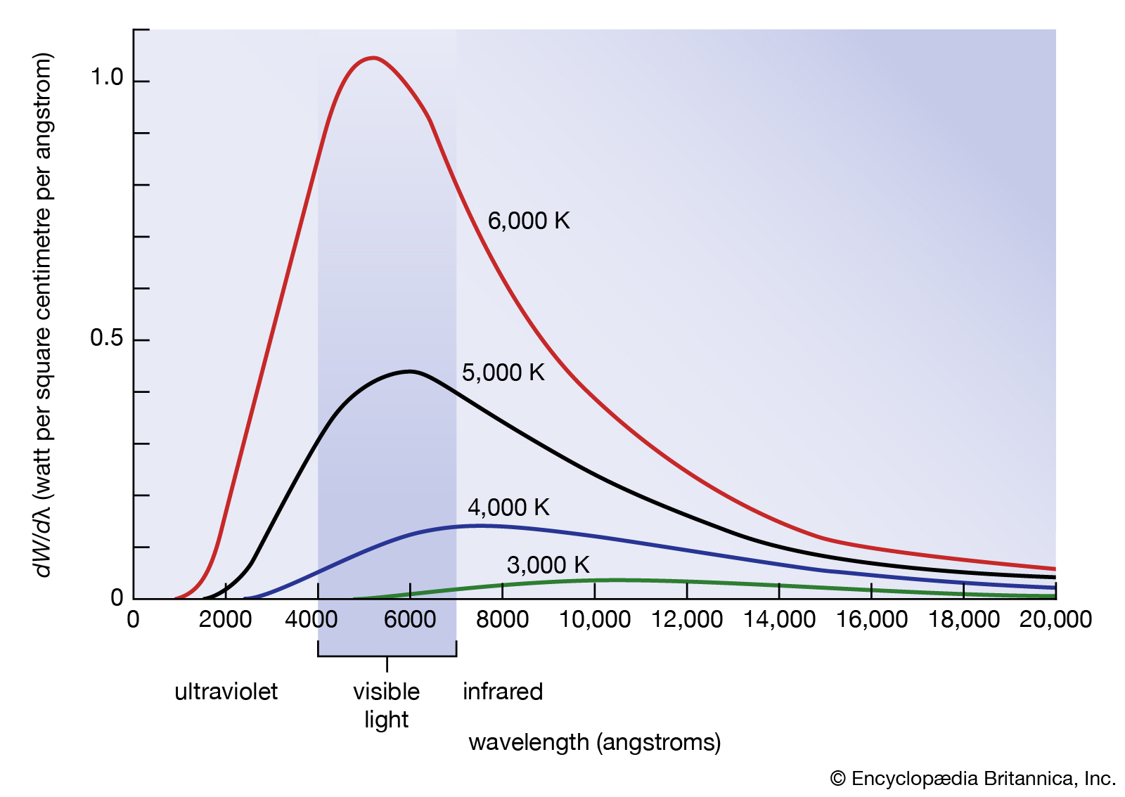
- Inconsistency: Wien’s displacement law was a successful model since it predicted the position of the peak wavelength.
- However, there were two problems:
- there was no theory explaining the curve shape of the intensity vs wavelength.
- Wien’s law was based on an ideal black body. Could this theoretical model represent the surface of a star?
- Classical physics predicted (black line) that intensity would increase infinitely as wavelength decreased into infinity however, when experiments were done, intensity dipped when it reached the UV spectrum despite a shorter wavelength, resulting in a curve.
- This could not be explained using classical physics and a new theory was required to solve this problem of ’the ultraviolet catastrophe.’
- As temperature increases, total energy should increase, and shorter wavelengths should approach infinity.
| Feature | Classical | Experimental Result |
|---|---|---|
| Behaviour at Long Wavelengths | Gradual decrease in spectral radiance/energy | Gradual decrease in spectral radiance/energy |
| Peak Wavelength | Gradual increase in power, no peak | Peak wavelength follows Wien’s displacement law, and depends on temperature |
| Behaviour at Short Wavelengths | Power approaches infinity, sharp increase | Power emitted is 0 at short wavelengths |
- In 1900, Planck began the era of quantum mechanics, a new branch of physics.
- His theory matched the experimental results with his formula: $E\propto f$
- He proposed that the vibrational energy of atoms in a blackbody was emitted or absorbed in discrete packets, or quanta.
- Rather than a continuous release of energy, at the peak temperature, a specific quanta escapes with a certain amount of energy (multiple of the Planck energy) (E = hf).
- Einstein theorised that light was also quantised in the same way, calling the ‘packets’ photons and using it to explain the photoelectric effect (E = hf)
- As heat inside increased, at each temperature a new packet of energy is released.
Photoelectric Effect
Planck’s quantum hypothesis that energy was emitted and absorbed in discrete amounts.
Albert Einstein put physical meaning into Planck’s quantum hypothesis by explaining the photelectric effect as the evidence for quantisation (E=hf).
The Photoelectric effect is the ejection of electrons from an electrode by incident light (aka light that is shone at a specific frequency onto a piece of metal causes electrons to flow or if a certain metal plate is irradiated with light at a certain frequency, an electron will be ejected which can be detected when it interacts with a positively charged wire).
The light must have a minimum/threshold/critical/cut off frequency $(f_0)$ for the electron to be emitted (x-intercept of max kinetic energy vs frequency on graph).
The ability for the electron to be ejected depends only on frequency and not on intensity.
If the photon energy is greater than the work function this goes into the kinetic energy of the released electron.
Philip Lenard observed that the frequency of the light caused a photocurrent through shining UV light through a quartz screen onto a zinc plate with variable voltage inside a vacuum tube and observing the current induced.
He observed that the photoelectric current (same as the rate of emission of electrons) is directly proportional to the intensity of light falling on the electrode but, to obtain zero current, the voltage has to be reversed to a certain V0 known as the stopping potential.
The voltage must be reversed to such an extent that the electrons cannot reach the anode.
This is the maximum kinetic energy an emitted electron can achieve.
He found that the intensity of the light did not impact their energy.
The larger the number of electrons, the greater the photocurrent.
The intensity of light is the number of incident photons (no. photons hitting metal) not frequency.
In 1905, Einstein used Planck’s equation of light along with the Law of conservation to explain the photoelectric effect (resulting in the Nobel Prize for Physics, 1921)
Einstein’s model has 4 components:
Energy of light is unevenly spread out over wavefront but concentrated in ‘packets’ or ‘bursts’ (photon)
Each photon has energy given by $E=hf,$ it cannot possess all amounts of energy, rather it is limited by certain discrete values hence causing ‘packets’
A photon could give up all or none of its energy to one electron. The photon could not give a part of its energy (wave model of light said energy could build up) i.e. all or nothing
One photon can liberate one electron as long as it can overcome the work function – there is no time gap
It explained how electrons could be ejected with very low intensity incident light at the right frequency, because it only takes one photon at the right energy to knock out an electron and also how increasing the intensity, increased the current but not the stopping voltage as greater intensity means more photons, but not more energetic photons – therefore more interactions produce more current but the average energy of the electrons is unchanged.
It also explained why increasing the frequency caused the stopping voltage to be increased linearly as a greater frequency $\rightarrow$ greater energy of photons $(E = hf)$ therefore each photon can transfer more energy to an electron.
Special Relativity
- In 1905, Einstein wrote 4 papers, one was on special relativity which did away with the aether (the medium assumed light travelled through) and there was no absolute reference frame.
- Einstein’s special relativity was based on two postulates (propositions).
- Special relativity only concerns things in uniform motion or stationary (inertial frames of reference).
Principle of Relativity
- The laws of physics are the same in all inertial (at rest or at constant velocity) frames of reference i.e. no aether was required as there is no absolute reference frame for which to compare our motion to, everything is relative, there is no universal direction.
- Newton’s Laws of motion and the SUVAT equations apply in any non-accelerating reference frame, whether or not there is velocity.
- You cannot do an experiment to determine whether you are stationary or in constant motion (both observers and movers have to assume they are not moving)
Constant Speed of Light
- The speed of light, $c,$ has the same value in all inertial frames in a vacuum.
- The speed of light does not depend on the speed of the source or the observer (speed doesn’t matter whether I’m moving the torch or not).
- $c$ is constant in a vacuum.
Evidence for Special Relativity
The Michelson Morley Experiment - Disproving the Aether

- Michelson and Morley intended to prove the existence of the aether by showing that light’s speed was different when their setup (as in the diagram above) was rotated, as a result of the motion of the Earth through the Aether (known as the Aether Wind)
- They expected to see an interference pattern on their detector, because light should have moved faster one way through the aether, but it didn’t
- The null hypothesis demonstrated that light did not require a medium to travel
- Einstein’s first postulate explained why this is false
Consequences of the Second Postulate
Time Dilation
- If the speed of light is constant to all observers, then two observers at different relative velocities will disagree on simultaneity (whether two events happened at the same time)
- This is because for the speed of light to remain constant, one of the observers will experience time as longer than the other observer
- This phenomena is known as time dilation, and if it doesn’t make sense, don’t feel bad: it literally took Einstein to figure it out
- Time dilation is determined by something known as the Lorentz factor:
$\orange{\gamma =\frac{1}{\sqrt{1-\frac{v^{2}}{c^{2}}}}}$
$\gamma:$ Lorentz Factor
$v:$ Speed of the moving observer $(\text{m/s})$
$c:$ Speed of Light $(\text{Constant, }3\times10^{8}\text{m/s})$
The Lorentz factor just represents the proportionality between the observed time of 2 different observers
Time Dilation is calculated by $t=t_{0}\gamma$ where $t_0$ is the time as experienced by the moving object, and $t$ is the time as experienced by the observer
- NOTE that you usually don’t have to rearrange this formula, because of relativity: from the moving object’s perspective, it is the observer that is moving
Length Contraction
- If velocity is distance over time, and time dilates but velocity remains the same, then distance should contract by the same proportion
- The formula for this uses the Lorentz factor from earlier too, because that’s our constant of proportionality:
$l=\frac{l_{0}}{\gamma}$
- Where $l$ is the length as seen by the observer, and $l_0$ is the length as seen by the moving object (this also usually doesn’t need to be rearranged)
- Note that length contraction only occurs along the axis of motion: if a cube is travelling at 0.5c, the sides parallel to the motion are the ones which will contract
Length contraction and time dilation are known as Lorentz Transformations. For those who like vectors:
Click here for the vector form of Lorentz Transformations.
The transformation can be parametrised by the constant $v,$ representing a velocity confined to the x-direction:
$$\begin{gather*} t\prime=\gamma\left(t-\frac{vx}{c^{2}}\right)\\x\prime=\gamma\left(x-vt\right)\\y\prime=y\\ z\prime=z \end{gather*}$$
Where $(t,x,y,z)$ and $(t\prime,x\prime,y\prime,z\prime)$ are the coordinates in 2 reference frames, and the prime frame is seen from the unprime frame as moving with a speed of $v$ along the axis $x,$0 along the axis $y,$ and 0 along the axis $z$, and $\gamma$ is the Lorentz factor $\frac{1}{\sqrt{1-\frac{v^{2}}{c^{2}}}}$.
Relativistic Momentum
Relativistic momentum can be derived from Newton’s second law:
Defining acceleration as $a=\frac{\Delta v}{\Delta t}, F=ma=m\frac{\Delta v}{\Delta t}=\frac{\Delta p}{\Delta t}$
Since the definition of force must be the same in all FORs, $\frac{\Delta p}{\Delta t}$ must be constant for all observers
Since force relies on time, time dilation should be includuded in the calculations:
$F_{\text{|proper time|}}=\frac{p}{t_0}=\frac{m_{0}v}{t_0}$
$F_{\text{|relativistic time|}}=\frac{p_v}{t_v}=\frac{p_{v}\sqrt{1-\frac{v^{2}}{c^{2}}}}{t_0}$
For Einstein’s first postulate to be satisfied, both values of F must be equal:
$F=m_{0}v=\frac{p_{v}\sqrt{1-\frac{v^{2}}{c^{2}}}}{t_0}$
Rearranging for $p_{v}:$
$p_{v}=\frac{m_{0}v}{\sqrt{1-\frac{v^{2}}{c^{2}}}}$
The Speed Limit of the Universe
- One of the consequences of special relativity is that an infinite amount of force is required to accelerate an object to the speed of light.
- As a result, it is impossible for an object with mass to travel at the speed of light. Time Dilation and Length contraction explain what happens to an object at that speed:
- An object approaching $c$ experiences virtually no passage of time, and length in the direction of motion is 0. From the object’s frame of reference, everything in the universe accelerates towards it, time stops passing, and the universe shrinks to a plane in the direction of motion.
- For a photon (which has no mass and therefore can travel at $c$), time has no meaning, and it is at the start, end, and middle of its journey all at once, and forever.
$E=mc^2$
Because Einstein wasn’t finished tearing up Newtonian mechanics, he also proved that mass is relative, depending on the speed of an object (which is why we’ve been using $m_0$ instead of $m$ to refer to rest mass)
He came up with an explanation for the effect of relativity on the mass of an object using momentum:
- Higher Velocity = More Momentum
- More Momentum = More Energy
- More Energy = More Mass
This resulted in probably the most recognisable equation in science: $E=mc^2$
This formula, known as the mass-energy equivalence principle, states that mass can be converted to energy and vice versa
The $c^2$ component is notable, because it shows that to form kilogram of mass, you need $9\times10^{18}\text{J}$ of energy, which is about the same as the amount of electricity used by South Korea in 2009.